Deflection (engineering)
In engineering, deflection is the degree to which a structural element is displaced under a load. It may refer to an angle or a distance.
The deflection distance of a member under a load is directly related to the slope of the deflected shape of the member under that load and can be calculated by integrating the function that mathematically describes the slope of the member under that load. Deflection can be calculated by standard formulae (will only give the deflection of common beam configurations and load cases at discrete locations), or by methods such as "virtual work", "direct integration", "Castigliano's method", "Macaulay's method" or the "direct stiffness method" amongst others. The deflection of beam elements is usually calculated on the basis of Euler-Bernoulli beam theory while that of a plate or shell element is calculated using plate theory or shell theory.
An example of the use of deflection in this context is in building construction. Architects and engineers select materials for various applications. The beams used for frame work are selected on the basis of deflection, amongst other factors.
Contents |
End load cantilever beams
The elastic deflection f and angle of deflection φ (in radians) in the example image, a (weightless) cantilever beam, with an end load on it, can be calculated (at the free end B) using:
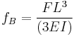
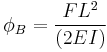
where
- F = force acting on the tip of the beam
- L = length of the beam (span)
- E = modulus of elasticity
- I = area moment of inertia
The deflection at any point along the span can be calculated using the above-mentioned methods.
From this formula it follows that the span L and height h are the most determining factors; if the span doubles, the deflection increases 2³ = 8 fold, and if the height doubles, the deflection decreases 2³ = 8 fold.


where
- b = width (x-dimension),
- h = height (y-dimension)
Centre loaded beam
The elastic deflection on a beam, loaded at its centre, supported by two simple supports is given by:

where:
- δ = the deflection of the beam
- F = force acting on the centre of the beam
- L = length of the beam between the supports
- E = modulus of elasticity
- I = area moment of inertia
Intermediately loaded beams
The elastic deflection on a beam supported by two simple supports, loaded at a distance a from one of the supports, is given by:
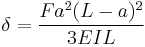
where:
- δ = the deflection of the beam
- F = force acting on the beam
- L = length of the beam between the supports
- E = modulus of elasticity
- I = area moment of inertia
- a = the distance of the load (F) from one of the supports
Structural deflection
Building codes determine the maximum deflection, usually as a fraction of the span e.g. 1/400 or 1/600. Either the strength limit state (allowable stress) or the serviceability limit state (deflection considerations amongst others) may govern the minimum dimensions of the member required.
The deflection must be considered for the purpose of the structure. When designing a steel frame to hold a glazed panel, one allows only minimal deflection to prevent fracture of the glass.
The deflective shape of a beam can be represented by the moment diagram, integrated.